Barbed Wire,Galvanized Barbed Wire,Barbed Wire Fence,Barbed Iron Wire Anping County Zhuodi Wire Mesh Products Co.,Ltd , https://www.hebzhuodi.com
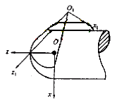
Fig.1 Principle of rake face machining 

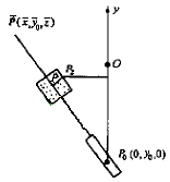
Figure 2 flank machining principle  ,
,  ,
,  }, cylindrical radius of the wheel is R1, there is
 ,
,  ,
,  }, then the P point trajectory equation is rP = r2 + R1t (8) then the straight line POP equation is rp = rp0 + l (rp-rp0) / (rp-rp0) (9) the intersection of this straight line and the plane y = y0 The trajectory is the model curve. Due to limited space, this article no longer lists the specific expressions of the above-mentioned mathematical models. It should be pointed out that the mathematical models given in this section are more concise than the corresponding mathematical models in other documents, and the corresponding model curves are easier to manufacture and easier to replace (in order to meet the needs of tools with different specifications), and thus have obvious advantages. Sex. When processing the flank, there is the problem of optimizing the selection of y0, R1 values. The principle of selection is to make the tool have a certain angle, but also to ensure sufficient strength at the edge. The specific treatment method is omitted here. 5 Conclusion The principle of non-numerical machining of the ball nose cutter and the mathematical model of the backbone have been successfully verified in the production practice. The ball-end milling cutter series developed in cooperation with Harbin Institute of Technology High-tech Park has been put on the market. In addition to the guiding significance of the low-cost mass production of ball-end milling cutters, this paper also has reference value for the mass production of other special rotary milling cutters mentioned in “Some Explanations on Spindle Milling Cutters with Two Axis Linkagesâ€. . However, it should be noted that the content of this paper only reflects the basic framework of the principle of non-numerical machining of ball-end milling cutters. If it is necessary to realize the processing method in the process, the corresponding non-backbone model needs to be filled according to other documents and the framework of this paper, and then be used again. Guide production.
Main mathematical model of non-NC ball-milling cutter
1 Introduction Ball-end milling cutters are important tools for CNC machining of complex surfaces (especially free-form surfaces). The market demand is large. Due to the complex shape of ball-end milling cutters, most of the processing of ball-end cutters at home and abroad are currently required to be implemented on multi-axis CNC machine tools. Due to the expensive equipment (up to millions of US dollars), the cost of one-piece tool processing is higher. high. In order to reduce the cost of tool processing, the author began to study non-numerical machining methods for ball-end milling cutters in 1991. Together with co-investigators, he proposed the mathematical model of the rake face and flank face of the ball-end milling cutter. Related machining model for ball end mills and serial production of ball end mills. In the in-depth research and development of ball-end cutters, in order to solve the more complex problems of the flank face grinding mechanism in the original machining plan, the use of a planar curved profile instead of a space curve profile to process and succeed, further reducing milling Knife processing costs. In order to have a general concept of the principles and methods of non-numerical machining of ball-end milling cutters by peers, this paper presents a summary of the machining principles described in several literatures and the related backbone mathematical models used to form the final products.