There are usually two ways to improve the accuracy of gear machining, one is to improve the manufacturing accuracy of the machine tool, and the other is to use error compensation to improve the machining accuracy of the machine tool. The gear machining error is caused by errors in the machine tool-tool-workpiece system. Therefore, to improve the machining accuracy of gears, it is necessary to analyze various factors that cause errors and take effective measures to reduce machining errors. The machine tool plays an important role in the gear machining process and has a direct influence on the precision of its machining workpieces. Improving the manufacturing accuracy of the machine tool itself is not necessarily technically and economically feasible, and often does not solve the machining errors caused by the workpiece mounting, tool and workpiece system forces, heat, wear and the like. Therefore, it is economically viable to improve gear machining accuracy through compensation control. Before machining the gear hobbing machine, you should do the following: (1) As the machining accuracy of gear blanks has a great influence on gear machining, inspection and installation accuracy, the machining precision of the reference surface of gear blanks should be strictly controlled, and the required tolerances for tooth blanks must be specified according to the new standard GB10095-88. (2) Process requirements before cutting teeth: The precision of the reference surface of the tooth blank has a great influence on the accuracy of the gears, so the processing technology of the tooth blanks should be strictly controlled. For the shaft gear tooth blank, it is better to leave the center hole at both ends, and both ends are turned on top to ensure that the outer cylindrical surface is concentric with the reference surface axis from the process. For larger shaft gears, a central hole is left at one end, and the outer cylindrical surface is formed in one loading. This minimizes the geometric decentering of the gear blank during cutting. For perforated gear tooth blanks, the process shall be specified in a single loading of the card, the outer circle of the inner hole and the end face shall be under one knife, and the end face under the knife shall be marked as the mounting reference when cutting the teeth. (3) Mounting of gear blanks when cutting teeth: The installation of tooth blanks must be carried out strictly in accordance with the reference surface of the process, and the error of alignment must be as small as possible to prevent geometrical eccentricity. (4)Adjustment of worm gear pair for machine indexing: When conditional, the indexing worm wheel pay for the machine tool should be adjusted regularly. The manufacturing accuracy of the machine indexing worm wheel can not be changed, but the installation eccentricity, the worm axis and the radial oscillation Can be adjusted, adjusted to reduce the tangential error and tooth shape error caused by eccentric motion. (5) sharpening and installation of the tool: sharpening of the tool is generally used hob grinder, so that the rake angle is zero to reduce the tooth profile error. For the installation of the tool, its radial runout and axial runout should be strictly controlled to reduce the tooth profile error. We installed an error compensation system on the Y3150E gear hobbing machine. The gear parameters are shown in Table 1. Table 1 Experimental gear parameters Gear number Modulus/mm Number of teeth pressure angle Helix angle Tooth width/mm 1 3 33 20° 0° 37 2 2.5 40 20° 0° 37 The accumulative pitch error before and after compensation is measured on the same universal tooth tool. Fig. 2 and Fig. 3 are the cumulative error comparison curves before and after compensation. Based on the above results, and according to the accuracy standard for involute cylindrical gears GB10095--88, the related accuracy indexes and analysis results of the front and rear gears are shown in Table 2 and Table 3. Table 2 before and after the accuracy of gear 1 compensation table Table 3 Accuracy before and after compensation of gear 2 (um) We compared the data before and after compensation using the error compensation system. The use of a hobbing error compensation system allows the movement accuracy of the machined gear to be steadily increased from 9-10 before compensation to 7-8 after compensation. Individual gears can be reached. Levels 5-6 increase accuracy to more than 2 levels. The accuracy of the work stability is steadily increased from the 7-level accuracy before compensation to the 5-level accuracy after compensation, and the accuracy is improved to 2 levels. The error compensation effects of the two precision indicators are all above 40%-70%, and the accuracy level is 2-4. The compensation effect is very obvious.
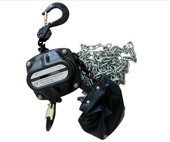
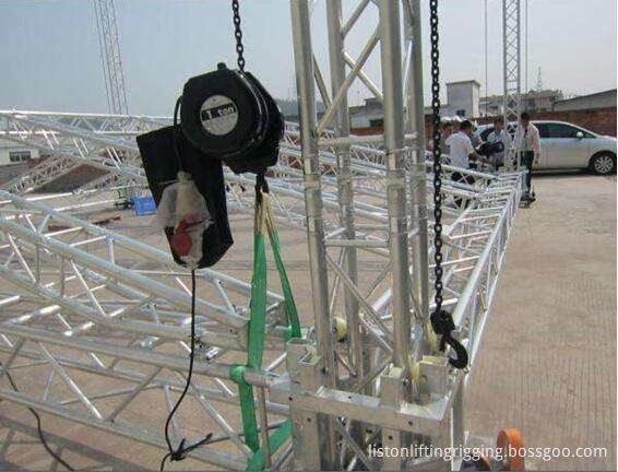
Manual Stage Chain Hoist is specially
designed & manufactured for stage inversion or common lifting
operation purpose. for example, in stage stereo, lighting,
show banner,
campaign activity and steel frame which application is
very wide.
1. Clutch: Protects hoist, operator, structure from damaging
overloads.
2. With Overload Protection: Designed to prevent
lifting of excessive overloads. Helps prevent lifting of dangerous loads.
3. Zinc plated
Load Chain to protect against corrosion. Optional black finish available.
4. Low voltage control: 24 and 48 volt optional.
5. Cast aluminum housing, lightweight. Black power
coated finish for low visibility.
6. 5-teeth Lifting Chain wheel
7. Double brake: With mechanical brake
Products ahow
Our Services
1.Client
We treasure and try to understand all the different needs of our clients and seek to forge a long term professional relationship with them. The satisfaction of each and every customer is our main goal and motivation in conducting our business.
2. People
We work as a team and treat each other with respect. Our solid, capable and knowledgeable team is valued as the greatest asset and an integral part of the business.
3. Product
Our products are of HIGH quality standards and always come with certificate of compliance by the manufacturers.
4. Performance
We aim to achieve high level of performance and satisfaction to both our client and people, which include delivering high quality services and treating people with integrity.
5. Free sample and OEM service
We can provide free samples to you and we also have OEM service, we can put your logo on the label and the information you need on the webbing too.
Stage Chain Hoist,Climbing Chain Hoist,Manual Stage Chain Hoist,Electric Stage Chain Hoist Hebei Liston Lifting Rigging Manufacturing Co., Ltd. , https://www.liftingriggings.com
After doing these tasks, we can use the error compensation system to compensate for errors and receive good results. The error compensation system is mainly composed of a microcomputer, a stepping motor, a speed reducer, an optical encoder, and the like (refer to FIG. 1). The system uses the measured pitch accumulated error as the compensation signal. After the data processing, the corresponding compensation control signal is generated in the microcomputer according to the established mathematical model. The signal enters the MCS-51 single-chip microcomputer system at the same time as the photoelectric encoder signal and the worktable zero signal. After data processing, the stepper motor drive system, stepper motor, and reducer are used to enter the differential chain of the machine tool. Go to the workbench and generate compensatory movements. In the compensation control, the angular displacement pulse signal of the photoelectric encoder is sent to the single-chip microcomputer system via the interface circuit as the signal for starting the A/D conversion. In terms of software, a point-by-point compensation method is used to convert the cumulative error of the measured left and right tooth profile to an angular error signal. After a series of processing, an error correction table is established in the single chip microcomputer. Compensation, each to a compensation point, according to the point of error correction, issued by the microcontroller to the corresponding correction pulse, drive the stepper motor to enable the workbench to drive the workpiece to generate additional rotation, in order to achieve the correction of the corresponding point. 


The hobbing process error compensation system has the advantages of simple structure, convenient use, low cost, stable operation, obvious compensation effect and the like, and provides an effective solution to the use and modification of the old hobbing machine. This error compensation system is not only suitable for the small and medium-sized gears used in industries such as automobiles and machine tools, but also has practical significance for the hard-to-face scraping processing currently widely used, especially for large gears and precision worm gears with hobbing as the final process. Processing is more significant. The principle of the system can also be applied to other machine tools with gearing requirements, such as gear grinding machines, to provide an economical and effective way to fully exploit the potential of excavator beds and retrofitting of old machine tools.


