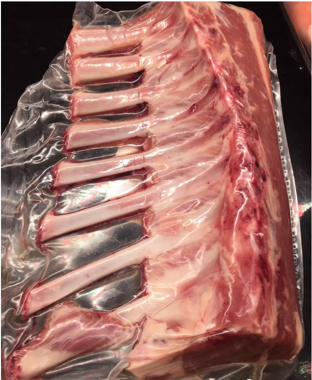
The Tipack Anti-Bone Shrink Bag features a proprietary anti-bone construction that resists punctures without the need for a patch, providing good value and high abuse performance for fresh, cooked and processed meats with bone. Ideal for heavily rubbed or flavored products, as edge-to-edge coverage and high-abuse materials are said to reduce leak rates and the number of repacks required. The clarity and gloss of the film makes it easy to print brand logos, cooking instructions, and more. Bags can be heat sealed or clipped to suit any retail or foodservice application.
No matter what special requests you have, we can offer customized service with our professional team in meat and food packaging industrial. If you would like to find out more about this product and our services, please contact us directly. Our friendly sales team looks forward to hearing from you and will gladly provide you with the personal support and information you require.
Ribs Shrink Bag,High Barrier Beef Steak Shrink Bag,Bone Guard Shrink Pouches,Barrier Bone Guard Shrink Bags Tipack Group , https://www.tipackgroup.com
(1) The hot spot of the thermocouple is not inserted into the end of the protective sleeve and is in close contact with the end. At this time, the temperature measured by the thermocouple actually only protects the air temperature in the cavity at the end of the sleeve.
(2) Improper installation of the protective sleeve failed to ensure that the hot spot of the thermocouple was within the measured temperature range. The reason is that the length of the protective sleeve is too long or insufficient, and the protective sleeve is not properly installed.
(3) When measuring higher temperatures, the part of the protective sleeve exposed to the air is not properly insulated and measurement errors are caused due to conductive heat dissipation.
Among the above three types of problems, the two types of problems (1) and (3) are relatively easy to solve. They can be avoided only by paying strict attention to the regulations in the installation process, and these problems can also be detected at any time during the operation. solve. As for the (2)-type problem, since the protection sleeve cannot be changed at any time after installation, it must be carefully considered in the design process and carefully constructed during the installation process.
It is generally believed that the temperature in the center of the pipe is the highest, and the temperature will decrease rapidly after deviating from the center of the pipe. Therefore, when installing the protective sleeve, the end of the protective sleeve is required to slightly exceed the center of the pipe to ensure that the hot spot of the thermocouple can be located at the highest temperature point. This makes the length of the protective sleeve inserted into the pipe larger.
The diameter of the main steam pipe of a large capacity unit is generally between 300 and 800 mm, so the depth of the protection pipe inserted into the pipe is approximately 150-400 mm. For thermocouples, this insertion depth is not large. However, for the protective sleeve, due to the high flow rate of the medium in the pipe, the temperature and the pressure are also high, and the poor working conditions are difficult for the protective pipe.
For medium-pressure units, the pressure is 4MPa and the temperature is 435°C: for subcritical units, the pressure is 18MPa and the temperature is 540°C; for all units, the flow rate reaches 40 to 60m/s.
Under the above working conditions, in order to increase the strength of the protective sleeve, it is necessary to increase the wall thickness of the protective sleeve, that is, the diameter of the protective sleeve. However, an increase in the wall thickness of the protective sleeve can, in turn, reduce the dynamic characteristics of the thermocouple. Therefore, the protective sleeve has to be tapered so that the end wall of the sleeve is thin and the root wall is thick. After this measure was taken, the thermocouple protection tube used on the main steam line of the unit still suffered frequent fracture accidents.
EBASCO Consulting has provided the maximum allowable insertion depth of protective sleeve made of stainless steel material 316SS (0Cr18Nil2M02Ti) at different temperatures, pressures and flow rates. See Table 1 for specific data. 
The data in the table is the only restriction on the strength of the material. According to the tabular data, it can be seen that the higher the medium pressure, the higher the flow velocity, and the higher the temperature, the shorter the insertion depth is allowed due to the limitation of the strength of the protective sleeve.
Second, hot-type electric couple 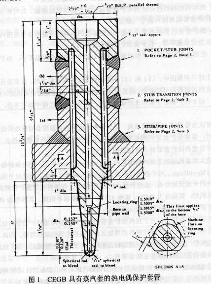
Under this circumstance, people began to consider shortening the insertion depth of the protection sleeve and intended to increase the reliability of the protection tube at the expense of measurement accuracy. But for the thermocouple on the main steam pipe, the measurement accuracy is the most demanding. Therefore, the idea of ​​shortening the insertion depth of the protective sleeve has not been implemented. In the early 1970s, the second edition of Modem PowerStation Practice, written by the Central Electric Generating Board (CEGB), was introduced to China. The thermocouple protection sleeve with steam jacket developed by CEGB was introduced in the book. As shown in Figure 1. There is enough room between the thermocouple protection sleeve and the mounting sleeve to act as a jacket. Steam entering the hot jacket can heat the protection tube. The middle of the protective tube has a triangular prism to ensure that steam can enter the hot sleeve smoothly. The prism is supported in the opening of the steam pipe to maintain the position of the thermocouple protection sleeve and allow the sleeve to change temperature Move freely in the axial direction. The protective sleeve is sized so that the hot spot of the thermocouple is at the centerline of the pipe. The purpose of developing such a protective sleeve is to reduce the time delay of temperature measurement. The time delay of the protection sleeve is smaller than that of the protection sleeve, and the test curve is compared with other protection sleeves.
Inspired by the CEGB-type protective sleeve, based on the current level of understanding, we believe that if the length of the steam heated portion of the thermocouple is constant, the impact of the depth of the inserted pipe on the measurement accuracy should not be significant. Under the guidance of this idea, in the mid-1970s, a thermal sleeve protective sleeve for measuring the main steam temperature was jointly developed by a research institute affiliated with the Ministry of Electric Power and a meter factory belonging to the Instrument Bureau of the Ministry of Electric Power. The structure of the protective sleeve is basically similar to the protective sleeve of the CEGB. To be on the safe side, to prevent the protection sleeve from falling into the pipeline after the fracture to cause a greater accident, the prism portion of the protection sleeve is tapered. During installation, the conical surface of the prism is pressed against the opening of the pipe to ensure that the prismatic conical surface of the protective sleeve is firmly fixed on the pipe wall. The structure and installation of the hot-jacketed protective sleeve are shown in Figure 2. The hot-jacketed protective sleeve was not found to be fractured when it was applied to the medium-pressure unit, but as the steam parameters continued to increase, the hot-jacketed protective sleeve also showed a fracture. 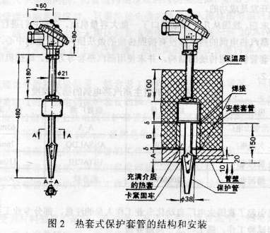
Third, the failure of the analysis of the thermal sleeve protective sleeve installation steps are as follows:
(1) Make a hole in the pipeline of the measured medium. In order to make the triangular cone surface of the protection sleeve securely mounted on the pipe wall, a 38mm diameter through hole can be drilled first and then expanded to a diameter of 42mm. When the hole is enlarged, the hole with a diameter of 38mm should be kept 10mm long.
(2) Welded mounting sleeve. The length of the mounting sleeve should ensure that the triangular cone of the protective sleeve is firmly seated in the 38 mm diameter hole.
(3) Insert the protective sleeve. When the triangular cone surface of the protective sleeve has been sealed with the 38mm hole, there should be enough welding gap between the protective sleeve and the mounting sleeve.
(4) Weld the protective sleeve on the mounting sleeve.
It can be seen from the structure and installation method of the hot-jacketed protection sleeve that during installation, it is required to press the prismatic taper of the protection sleeve tightly on the opening of the pipeline to ensure that the prismatic conical surface of the protection sleeve is firm on the pipe wall. Fixed. When the temperature rises, because the temperature rise of the protection sleeve and the mounting socket is different, the temperature of the protection sleeve is obviously higher than that of the installation socket, and the expansion of the protection sleeve is also larger than that of the installation socket. However, the hot sleeve protective sleeve is installed so that no displacement can occur between the protective sleeve and the mounting sleeve. Therefore, during the operation of the unit, the protective sleeve is always subjected to compressive stress, and the mounting socket is always subjected to tensile stress. After long-term operation and multiple start-stops, the casing can be damaged due to the stress. In the medium-pressure unit, due to the strength of the material is sufficient, the possibility of fracture is small; when the pressure is increased, due to close to the material's strength limit, the fracture can easily occur.
Fourth, the effect of thermal sleeve type thermocouple After using the thermocouple type thermocouple, the insertion depth of the thermocouple to measure the main steam temperature has been reduced from about 150mm to about 80mm. In order to clarify the effect of the thermocoupled thermocouple, several comparisons have been made with thermocouples inserted into the pipe centerline. As a result of the comparison, the difference in measured temperature for two thermocouples with different insertion depths was not greater than 3°C and did not exceed the allowable error of thermocouples. As the distribution of the medium's softness in the pipeline was not well understood at the time, it was erroneously considered that the development of the thermowell-type thermocouple protection sleeve was successful.
In the late 1970s, China imported a large number of large capacity units from several countries. After investigating them, it was found that the hot spots of the main steam thermocouples of all the units were not inserted into the center of the pipeline according to the traditional practice, and the insertion depth was shortened, but the protective casing still used the traditional structure and steam was not used. Hot sets and other methods. The insertion depth of the main steam thermocouples of these units is shown in Table 2. 
This situation has aroused the attention of the automation professional staff of thermal power plants in China, and some professional engineers and technicians have conducted a lot of analysis and test work, and finally solved this problem.
V. Temperature Field of Steam and Water Fluids The temperature field in the pipe along the diameter of the fluid changes with the flow rate of the fluid. When the flow rate of the fluid is low and the Reynolds number is lower than the critical value (2200), the flow of the fluid is laminar. The flow rate of fluid in the pipeline is the highest in the center of the pipeline. After leaving the centerline, the flow rate will decrease rapidly and change parabolically along the diameter of the pipeline. The temperature distribution on the pipe section is similar to that of the flow rate, and the center temperature of the pipe is the highest. The closer to the pipe wall, the lower the temperature. Its temperature field is also similar to a parabola, as shown in (a) in Figure 3. Therefore, when measuring temperature in a laminar fluid pipeline, the hot spot of the thermocouple must be accurately positioned in the center of the pipeline. 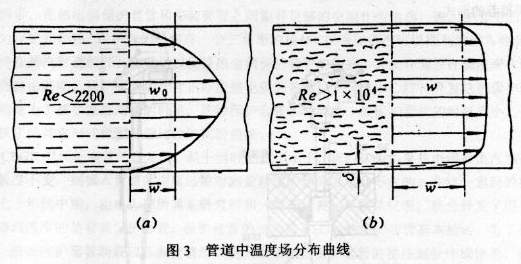
When the fluid velocity in the pipeline is high and its Reynolds number exceeds a critical value, the fluid flow is turbulent. At this time, the interaction of fluid molecules in the pipeline is enhanced so that only a thin layer of fluid that is in close proximity to the tube wall maintains laminar flow characteristics. The flow velocity in most sections of the fluid is almost the same, and the temperature field in the pipeline is also similar, as shown in Fig. 3(b). Therefore, when measuring temperature in a turbulent fluid pipeline, the temperature of the fluid can be accurately measured simply by inserting the hot spot of the thermocouple into the isothermal region of the fluid, and the insertion depth does not need to reach the center of the pipe at all. According to the test results on a 200 MW unit, for a main steam pipe with a diameter of 273×20 mm, the hot spot of the thermocouple can be inserted into the isothermal zone of the fluid by inserting 50 mm into the pipe.
According to the above theoretical analysis and test results, combined with the conditions of the imported units listed in Table 1, it can be seen that when measuring the temperature in the turbulent fluid pipeline, the insertion depth of the thermocouple protection sleeve is selected to be between 65 and 90 mm. Accurately measure the fluid temperature. At present, the insertion depth series of thermocouple protection bushings on the market are generally 50, 100, 150 mm, etc. For the sake of safety, it is obviously most reasonable to select the insertion depth of 100 mm.
In order to improve the reliability of thermocouple and thermal resistance protection sleeves, the temperature of high temperature and high pressure medium such as main steam temperature, reheat steam temperature and feedwater temperature can be measured in the thermal power plant to reduce the insertion depth of the protection sleeve. Way to measure. The Reynolds number of the medium in these pipelines during operation is always above the critical value.
6. Conclusions (1) Due to material strength limitations, the insertion depth of the thermowell protection tube is limited in high temperature, high pressure and high flow rate pipelines. In most cases, it cannot be inserted into the pipe centerline.
(2) Due to the temperature distribution characteristics of the high-speed fluid in the cross-section of the pipe, the temperature of the medium in the pipe can be accurately measured when the insertion depth of the thermocouple protection sleeve exceeds 50 mm in the high temperature, high pressure and high flow rate pipelines.
(3) The specially developed hot-jacketed protective sleeve does not help to accurately measure the temperature of the medium in the pipeline. On the contrary, it may also bring accidents and there is no value in continuing to use it.
(4) When measuring temperature in high-temperature, high-pressure and high-flow pipelines, it is recommended to adopt the internationally accepted form of protective casing. Two more common ones are given in Fig. 4, where (A) is the recommended form of the EBASCO consulting company and (B) is the recommended form of the BABCOCK company. 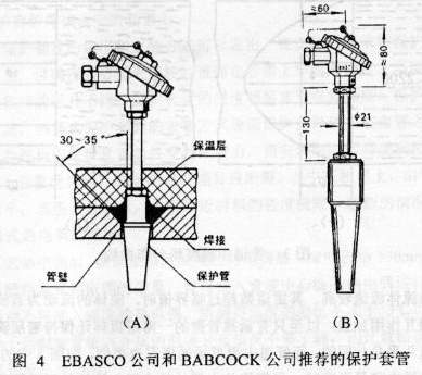
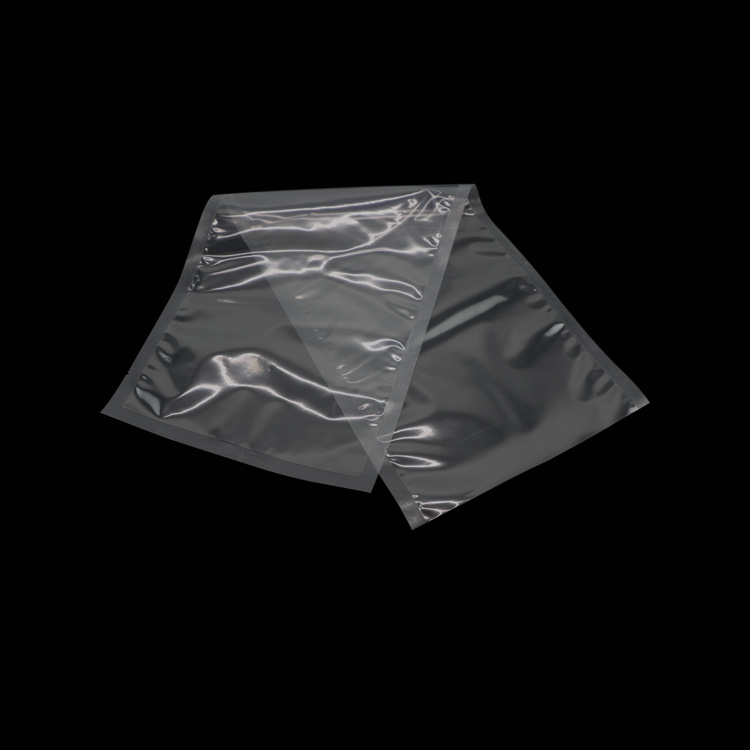
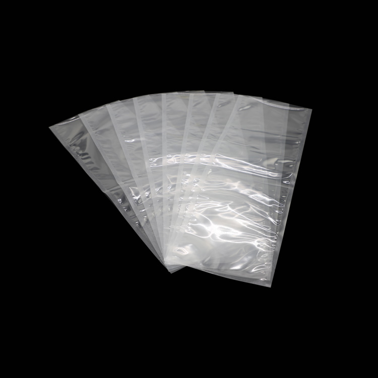
Tipack high-barrier shrink bag is a nine-layer vacuum shrink bag, which can effectively block oxygen, maximize the shelf life, and enhance the value of the product. Available in a variety of sizes for direct food contact. We can customize any size you want for large quantities and provide standard sizes for most customers. Tipack high-resistance thermal shrink tape can also be printed, which can meet the needs of customer brands, we use the world's most advanced printing technology, double-sided printing 10-color flexo.
Our heat shrinkable bags have very high transparency and shrinkage rate, which makes the appearance of the products more beautiful and increases the sales of goods.
Here are the standard widths, 165mm, 180mm, 190mm, 205mm, 225mm, 250mm, 275mm, 300mm, 325mm, 350mm, 375mm, 400mm, 425mm, 450mm, 475mm, 500mm. And the length can also be any size you want. Thickness: 50-80um. Color: Transparent, or match PMS bulk. Printing: We also provide printing services for flexible packaging machines, the machine can print 10 colors on each side at the same time. Tipack bags maintain superior shrink performance by balancing high shrinkage with low shrink force. The bag shrinks to the product shape, creating a wrinkle-free package that retains the product's original shape. Our shrink bags are widely used for beef, lamb, pork, turkey, poultry, tuna, cheese, processed meat, fresh meat.
All production facilities and processes are FDA, BRC and HACCP/ISO certified to ensure food contact safety. We provide one-stop service, high barrier shrink bag/film, EVOH fruit cup, EVOH/PP sheet, PA/EVOH/PE Thermoforming Film, PA/PE Thermoforming Film, MAP/plastic/VPS tray, osmotic shrink bag / film, high barrier film, absorbent meat pad, vacuum machine.
Barrier packaging is used when the inner product needs to be protected from aromas, tastes, gases, light, oils, oxygen, water or water vapour. A variety of materials are available, including polyethylene (PE), PVDC, and ethylene vinyl alcohol (EVOH). PE and PP materials provide a moisture barrier. Typical PE applications include breathable packaging or carton liners for fresh produce. It is most commonly used in plastic bottles, meat and cheese packaging, snack food packaging, bagged boil or serializable pouches. PVDC, EVOH provide oxygen, gas and aroma barriers. It is a modified atmosphere packaging for oxygen sensitive food.
Analysis of Heat-set Thermocouple Operation
First, the error caused by the protection sleeve in the thermocouple temperature measurement process The error in the temperature measurement process of the thermocouple installed in the protection sleeve, in addition to the error of the thermocouple itself, the error caused by the protection sleeve can not be ignored. There are three main sources of error caused by the protective sleeve: